Mobile phone is not a phone anymore. It is a device on indispensably daily and multipurpose use. Nowadays high-end phones capability are brought to many consumer groups in different affordable levels. It is right to say that lower cost high-end devices should be target for OEMs for the next a few years.
However, smart device does not function enough without ecosystem, other than being a communication and calculator tools. Therefore, without cloud, OEMs shouldn’t omit the possibility to have big challenge: The cloud owners that are likely targeting to increase their market share through including the devices into their ownership list. Only some applications could be gateway for cross-cloud access but not in fully broad ways.
Emerging markets like Asia, Africa, South America would progress toward device and ecosystem pair much faster, and therefore targeting low cost smartphone might not serve OEMs in long term. May not be profitable either due to higher competition. Slowdown in Europe economy should be taken into account as well.
In additions, large companies that have cloud, or capability for cloud, might hop in the device market as well, covering both high end and low cost devices with more connected functionalities.
What could help OEMs? It could be independent clouds with different services and widely standardized application interfaces.
Friday, July 27, 2012
Tuesday, July 24, 2012
Fundamentals of Radio Control - Basic Elements
Duplexer

Duplexer is a passive RF component which isolate Rx and Tx signals while they are using the same antenna.
The signal from to Tx port to Rx port is attenuated. The attenuation is called Tx Rejection. In addition, Tx noise contains spectral energy in Rx band. This needs to be rejected before reaching to the antenna port. This is called Rx rejection. The rejection varies about 40dB to 60dB.
The signal passing through from antenna to Rx port in downlink frequency band, and the signal passing through from Tx port to antenna in uplink frequency band are subject to small loss, called Insertion Loss, which is generally about or below to 2dB.
RF Switch

RF switch is sued to multiplex multiple RF ports to one RF ports. In a common case, multiple RF RX and Tx ports are multiplexed to a single antenna. The key parameters are the insertion loss between RF ports and antenna, the isolation between RF ports. A few bit digital ports can be used to control the switch configuration.
Power Amplifier

Power Amplifiers, or in short PA, is used to amplifies the RF signal prior to antenna. RF signal amplification starts from mixer, and may continue with RF drivers within RFIC. The signal amplification level at output RFIC is less than the maximum allowable power levels from antenna, therefore an additional power amplification stage is needed in most cases. In 3GPP WCDMA/HSPA standards, the maximum power level of a user equipment is defined to be 24dBm. RFIC in this field provides maximum of about 5 to 8 dBm.Assuming about 1dB loss from output of the power amplifier to the antenna port 17 to 20dB gain is required from PA.
One of the main concern in PA is the efficiency. In order to increase efficiency many techniques have been developed and commercialized. Discrete gain modes, adaptive discrete or continuous bias signal level, adaptive power supply to PA stages are some examples. Amplitude tracking is another method.A DC/DC converter can be used to provides variable power supply voltage to PA. All these controls are shown in basic form in the figure above.
Some PA or PA modules can support multiple bands, and this is controlled by an interface signal.
Power Detector and Maximum Power Control

The gain of the Tx path can be degraded due to temperature and therefore a calibrated gain mapping cannot help to make sure that PA is delivering maximum allowable power level when needed at the edge of cell coverage or more generally at the poor coverage areas. On the other hand, the maximum power level is also mandated by the regulations due to radiation hazard to human being and interference control within the wireless network. Therefore additional closed loop maximum power control can be used to solve these concerns, as shown above. Power detector samples the signal level at the output of PA and produces a voltage at its output, which can be sampled with an ADC. The curve can be obtained by the calibration which maps the reading level at the output of ADC to certain power level at PA. An algorithm determine a dynamically varying maxim gain control at the baseband/modem within RF software driver. This power control works with assumption of low sensitivity of power detector to temperature.
Low Noise Amplifier (LNA)

Every component at a receive path in an RF subsystem add some noise to the signal. LNA is an amplifier used at early stages on the receive path to amplify the signal before other components between LNA to the modem add noise. It may have programming for
- Band of operation
- Change the gain between multiple discrete gain levels.
Filters

Filters are used both on receiver and transmitter paths at RF system designs. They are two port components and they designed for specific band of operations. The filter passes the signal at designated band and attenuate all the other outside of the designated band. SAW (Surface Acoustic Wave) filters or BAW (Bulk Acoustic Wave) filters are commonly used in RF. BAW filters are relatively requires more complicated fabrication, and therefore they are not cheaper than SAW filter. However, BAW filters are known with sharper filtering. There are many parameters important in the characterization of a filter. The main ones important in RF radio control are:
- Insertion loss (less than 2dB in general, the loss within the designated pass band)
- Badwidth (The spectral with of the pass band)
- Rejection (The attenuation out side of the pass band)
Multiplexers

Multiplxers are used instead of antenna switches at some RF designs. It connects multiple RF signals to a single RF antenna, or single RF port. No programming is needed. Multiplexers are called according to the number of RF ports.Diplexer has two RF ports, triplexer has three RF ports, quadplexer has four RF ports and quintplexer has five RF ports other than antenna port.
Previous
Next
Tuesday, July 10, 2012
Fundamentals of Radio Control - Basics on RF Software Drivers
Introduction
RF software drivers main functions are as follows:- Performs the initial programming of modules in RF system after first power up.
- Control supply and clock for RF system.
- Activate, de-activate and programs the parts of RF system for desired operation.
- Performs gain control (Some of this functionality may be done at DSP/ASIC level, outside RF SW driver.)
- Programs the compensations of temperature and frequency dependent variations.

Receiver Activation - An Example
Here is an example of receiver activation procedure:- Enable power supply for active components such as frequency synthesizer, LNA, receiver IC.
- Wait a few microsecond to make sure that the supply outputs are stable. Otherwise, programming attempt in the next step may fail.
- Program synthesizer to certain band and channel of operation and program any compensation values for certain components if necessary.
- Program any other device to the desired band of operations such as antenna switch, receiver IC.
- Wait for synthesizer complete acquisition to the desired frequency, and all internal on-chip compensation procedures completed. Otherwise the reception may include some undesired initial part.
- Apply gain distribution among gain stages for the expected signal level initially.
- Enable reception.
The Order of Events Matters
The events controlled by RF drivers must be in a right order. Some rules are as follows:- Do not enable receiver before the frequency synthesizer is on and locked.
- Do not enable signal at the output of transceiver before power amplifier is on and ready to amplify.
- Do not program a device before its power and its clock ready.
- If a PA has multi-mode, program its mode prior to activation.
The Timings of Events Matters
Every components on an RF path has a non-zero time response. the air signal frames/slots has certain time boundaries. Therefore, the events controlled by RF SW drivers must be timely. Some rules are as follows:- If a receiver must be on for a time frame, the RF driver has to start the activation procedure not late and not early:
- Not Late: make sure that the desired signal segment on time axis has been sampled by the receiver.
- Not Early: Make sure that receiver does not consume battery for a time interval unnecessary.
- The time between enabling power supply for a device and the supply output being ready is not zero. A transition occurs. Wait for a few microsecond before programming the device.
- The time between enabling a TCXO or a frequency synthesizer and the clock be ready for use is not zero. A transition occurs. Allow the transition passes away before assume the clock or oscillation is on.
- If a RF device has on-chip calibration before activation, wait for the device to complete.
- Gain in receivers and power at transmitters may be allowed to be changed at certain time segments. Initiate gain and power change procedures timely, and make sure the procedure completed within the desired time segment.
RF System Bring-up
In most design when HW be ready in the lab and SW is mature enough for functional operation, RF system bring-up is one of the first task to be done.Hardware Check
Review the RF block diagram, signal flow, GPIO assigned to RF functions, power rails assigned to RF system. Identify the details to be check with software.Software Check
Revise GPIO assignments with polarity. Such as control outputs to RF switches. Review power rails and their enable/disable functionality. Check all RF features controlled for each main use case such as GSM Band 900 transmission.Calibration and Parameter Check
Make sure that default calibration data make sense in value for the target operation. At the first RF bring-up the calibration may not be perfect. Make sure all the RF related fixed parameters and features are defined.Connected Receiver Test
Check one mode and one band and one channel to test Rx:- Apply signal at the main antenna port, and check the RSSI value
- Change the signal level at certain dB and see RSSI is changing almost the same amount
- Check the current draw when Rx is off and Rx is on. There must be some difference when Rx start to operate. If you cannot see the current consumption change, check the power rails to RF circuit if they are on when Rx is set to on.
- (If you do not see RSSI and current change) Turn off the signal generator and check with high impedance RF probe and spectrum analyzer if frequency synthesizer is turned on and you read correct frequency. If you cannot read local oscillator frequency, than try other channel, bands and modes.
- If Rx is working, repeat the test above several time to make sure that the operation is stable
- Repeat the test above for different channels within the band
- Repeat the test above for other band and modes
Connected Transmitter Test
Check one mode and one band and one channel to test Tx:- Connect the radio to a spectrum analyzer, and adjust it for the test frequency
- Set the mode, channel and transmit power to a lower value. Enable Tx.
- Check the spectrum analyzer if signal is visible with the expected waveform bandwidth.
- Increase power by a certain dB and check the signal level at the spectrum analyzer screen. The signal level should change almost the same amount you changed the power.
- Check the current draw when Tx is off and Tx is on. There must be some difference as a function of power level. If you cannot see the current consumption change, check the power rails to RF circuit if they are on when Tx is set to on.
- (If you do not see the signal and current change) Check with high impedance RF probe and spectrum analyzer if frequency synthesizer is turn on and you read correct frequency. If you cannot read local oscillator frequency, than try other channel, bands and modes.
- If Tx is working, repeat the test above several time to make sure that the operation is stable
- Repeat the test above for different channels within the band
- Repeat the test above for other band and modes
Call Loopback test
Check one mode and one band and one channel:- Check if the radio is programmed for the desired mode, band and channel
- Connect communication tester and adjust its parmeters
- Set downlink signal level into mid levels around -70dBm to -50dBm.
- Make a loopback test
- Check if RSSI reading is almost the same as expected, but aware that there could be differences due to calibration errors.
- Check uplink modulation accuracy, frequency error
- Do frame error rate test at different downlink signal strength varying from sensitivity level to the maximum allowable signal level.
- Repeat the test above for different channels within the band.
- Repeat the test above for other band and modes
RF System Debugging
When an issue comes to table, it is difficult to determine the start point for debugging. A good observation with detailed report helps very much. Any interpretation without solid observation leads to longer debugging and fixing process.Here are some possible causes to be kept in mind all the time:
- Test setup is not appropriate and observation is wrong.
- HW may cause signal interference (over radiation and conductive coupling)
- Noisy power supply
- Sensitivity to temperature
- Problematic programming interface (serial link).
- Procedure/calibration setup has some issue
- Calibration data are not stored correctly
- NV items are not read correctly and or compensation tables may not be updated correctly at power up.
- Some other fixes/changes in RF and in other areas may have side effects.
- Understand the problem description completely. If it does not make sense or if it is not complete, ask for the reporter for better description.
- You may check if the issue is repeatable.
- If it is repeatable, re-generate the issue and make more observation with some different parameters and conditions. For example change the channel.
- Narrow-down the possible areas as much as possible.
- If it looks like a HW related, work with HW engineer closely.
- If it looks like a calibration issue, work with calibration engineer closely.
- You may add new log messages to get more info or an indication with more frequency, such as LNA state, PA state.
Sunday, July 8, 2012
Fundamentals of Radio Control - Architectural Overview
The figure below illustrates three main blocks: (1)
UI&Applications; (2) Modem/Baseband and Protocol Stack; (3) RF
system. The former block is non-signalling part that may include some
radio operation part such dialer, call manager.

Modem, sometimes we call baseband, and protocol stack can be mapped to Layer 1, Layer 2 and Layer 3 radio operation if this radio supports 3GPP standards. Layer 2 and Layer 3 are upper level protocols, we sometimes call it as protocol stack. It is responsible on radio operation resource control, link establishment, handover, etc... Layer 1 is signal processing layer, we may call it physical layer. The modulation, error-control coding, the signal timing synchronization, signal phase synchronization, low level transmit power control, low level receiver control are done within Layer 1. It is strongly related to radio control.All very time sensitive radio control operations done in ASIC blocks or fast digital signal processors within this layer.
Some high level radio control are done on RF software drivers, mostly run on a processor with protocol stack. The time sensitivity is about more than 100 microseconds. It programs RF system to system level specific use-cases, such as enabling/disabling receiver, programming the system to certain band and channel, monitoring RF system and applying adjustments.
Depending on the partitioning, the radio control functions to be done within Layer 1 and RF software drivers vary in large. A general trend towards high speed transmission, more functions becomes more time sensitive, and therefore many functions needs to be done either in ASIC hardware or in high speed DSP. In the past, most of the power control, maximum power control, receiver gain control were done in RF software drivers. In current systems these are part of Layer 1.
We have additional three important functions. One of them is clock management. It mainly controls the reference clock and all generated clocks distributed to multiple design blocks including processors, signal processing blocks. From the radio control aspects, it is related to reference clock supplied to radio, reference clock tuning, frequency synthesizer operation and RF clock generation.
Power management controls the power distribution to design blocks. For better power consumption management, power is supplied on the design blocks needed to be active in an operational mode. Radio part also has multiple design blocks and the power supplied or turned off to these blocks depending on the mode of operation. For example, if the radio is in idle mode listening the system time to time, the power management may keep the transmitter design blocks off, and enable the receiver design blocks time to time, whenever the radio listens the system.In today's radios, multiple power rails distributes the power supply in a tree structure with multiple branch point on a path. power management function is also distributed over this tree-topology. A radio can have different power rails for frequency synthesizers, power amplifiers, digital to analog, analog to digital signal converters, receiver amplifiers, ...
As the complexity of the operation increases, the diagnostic becomes inevitable. During system testing, or during the regular operation, radio control diagnostic collects the information on signal and events. The logging of these information during lab and field test provides tools for issue debugging. Even in the regular operation, at the end of end users, the diagnostic can still collect and stores the detected errors, and assist for debugging. Some of diagnostic information are received signal level, transmit power, transmitter enabled/disabled, receiver gain level, operation channel, operation band, operation mode.
The radio system have five main blocks: Receiver, transmitter, frequency synthesizers, RF front-end, and antennas. Antennas can be considered as a part of RF front-end or independent. In this sequel, we prefer to separate them from RF front-end.
Receiver and transmitter are self-descriptive. The transmitter converts the baseband signal at the output of Layer 1 to RF signal that can be radiated over antennas. The receiver transfer the perceived signal radiation from antenna to the baseband signal and provide to the input of Layer 1. The reason of conversion from baseband to RF, and RF to baseband is due to multiple reasons. Radiation over small size antennas, and propagation of the signal over the air requires higher frequencies. Excluding special radio transmission systems, most of the radio operation occurs more than 100kHz. FM radio channels is around 100MHz, cellular radio operation is mainly between 400MHz to 2.5GHz. HF transmission needs frequency range from 3MHz to 30MHz the signal to be propagated through the ionosphere.
Frequency synthesizers generates pure, actually approximately pure, sinusoidal RF signals. these signals are used to carry the baseband signal to RF frequency bands. An RF frequency band may be partitioned into many frequency channels. the tuning of the frequency synthesizers determined by the band of operation and channel number within the band of operation. Radio control configures the synthesizers accordingly.
RF front-end does not describe a definite object. It is between antenna and transceiver, or RFIC, where, transceiver may include the transmitter but no power amplifiers, receiver with or without low noise amplifiers, frequency synthesizers. Although some integration attempts is ongoing to add more RF front end into RFIC, economically and technically still there are many reasons to keep RF front-end outside of the integration today. Successfully Low Noise Amplifiers (LNA) have been integrated into RFIC but still in some designs and some interference in the operational environment, external LNA can be used. In the following sections, RF front-end will be explained in more details.
Previous
Next
Fundamentals of Radio Control - Introduction
Radio software control requires understanding of RF systems at
functional level. RF architecture and components vary depending on the
target operation, the target performance, the cost. The target operation
is most complicated factor that is a composition of can be split many
sub-factors such as operation frequencies, operation mode, possible
interferences in the operational environments, operation bandwidth. In
today's cellular phones, more than one radio operation mode, and more
than one operation frequency bands are supported. We call "multi-mode and multi-band"
radio operation. The optimized RF architecture becomes more
complicated, and therefore subject to more challenges in design and
control.
In this sequel we give an overview of the fundamentals on:
In this sequel we give an overview of the fundamentals on:
Fundamentals of Radio Control - Functional Overview
Downlink and Uplink

Duplexing
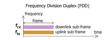
Duplexing allows simultaneous communication between uplink and downlink. There are two basic types of duplexing: (1) Time Division Duplexing (TDD); (2) Frequency division duplexing (FDD). The duplexing allows simultaneous services between downlink and uplink. Assume that a video streaming from downlink, and a picture uploading at uplink. A voice call with the duplexing makes the conversation more interactive.
TDD uses single frequency band and shares it between downlink and uplink. The durations of dwell time in downlink mode, and uplink mode are in the multiple of 1 milliseconds in LTE-TDD. The switching time becomes critical and it takes 1 ms in LTE-TDD. There are many other challenges in LTE-TDD but its benefit is more flexible resource assignment between uplink and downlink.
Frequency Spectrum and Channels
The frequency regulatory bodies like FCC in USA, ETSI in Europe, TELEC in Japan, designate the spectrum in their geographical regions. Within their region, they arrange the spectrum available according to the target technologies, market areas (either national, or regional). 850 MHz Cellular band in USA, 900 MHz Cellular band in Europe are some examples. These are arranged as FDD. Band 40 in 3GPP is LTE-TDD band.Channel raster is the minimum resolution of carrier frequency arrangement. In 3GPP system it is 200kHz. The numbering is done according to the left edge of the band and the raster.
Previous
Next
Sunday, July 1, 2012
Tangible User Interface
It looks like the tangible user interface is reforming digital media into physical elements and events rather than flat touch displays, keyboards, mouse. The concept is not new. It goes back to early 1990s. It is an active research field and many companies are working. Some references indicates Microsoft, Apple, Oracle are among these companies along with the universities such as MIT, Berkley, Georgia Tech.
There are several demonstrations. You can see more from the following links:
Tangible_user_interface at Wikipedia
Tangible user interface at MIT Media Lab
For initial idea, you may watch the following video:
Tangible user interface is another milestone on the path of the convergence to bring digital media to be more accessible and utilizable. Some of us remember the old big computer centers, green screens, keyboards used to type commands in a command line interface.When graphics come to life, we started to see the graphical user interfaces, mouses. It took some time to enable the graphical user interface from the boot of the computers. At the earlier stage, we were launching the graphical user interface by a command on command line. There were the first graphical word processors launched from command line interface. Not everyone could able to use a computer at those days.
Many business applications were developed on text screens, with limited number of symbols in ASCII set used to draw rectangular frames, to create bold-unrealistic shadows to give a pseudo 3-D feeling.
Then graphics became more advanced and commercialized into the small cheap computers, we saw the operating systems moved into full graphical user interfaces, and emulate the command line as a window in the graphical user interface. The usage of computers became much easier. No need to learn complicated command-line commands, their syntax. Everything was one click away.
When we saw the touch screens in bank ATM machines, most of us newer thought that it would be another milestone in user interface. The technology have been progressed in high speed, and now we see touch screens in every place. Our kids are trying to execute some icons on computer or TV screen by touching. When it doesn't work, asking why.It is so natural. They want to touch them like in physical world, pressing to a button.
Here we see, we are at the age of natural user interface, tangible user interface; another milestone. We want to access everything in digital media like everything in physical word. It seems clearly this is the natural path we have been coming a long time.
Subscribe to:
Comments (Atom)
